Since my last update more than two months ago, I have made many improvements to Fusor 1. Most significantly, I have finally replaced the HVAC pump that has been a near-constant headache since the beginning of my project. The Precision D-25 pump that I replaced it with is a much higher quality belt driven pump actually designed for scientific use and capable of attaining a deeper, cleaner vacuum.
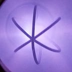
With this new capability, I have begun to observe a very interesting plasma state called “Star Mode” where beams of plasma emanate out of the grid in a star pattern (for a geodesic grid). In this state, ions exhibit notably different behavior than in other modes of operation that I would like to study further.
Although my system is still powered by an NST and runs on air, I am beginning to touch upon the range of conditions needed for fusion which is very exciting.
Oil Leaks from the Old Pump
At the end of my last update, I mentioned that some sort of residue appeared on the inside of the viewport. Unfortunately, that residue was, in fact, liquid oil that had been ejected into the chamber. It was even worst than I had feared as there was enough oil for it to pool inside the chamber.
Not only does spraying liquid oil into the chamber dirty it and contaminate the gaseous environment, having oil in the chamber could limit the vacuum that I am able to reach. Although the pump itself is unlikely to pull a deep enough vacuum to make the oil evaporate, heating from plasma when the fusor is in operation could push it over the edge which would increase the chamber pressure significantly.
Instead of fully disassembling the chamber, I opened two 6" flanges to clean out the oil which seemed to work well enough. Subsequent runs saw similar levels of vacuum as those before the oil would have had time to accumulate.
At the time, I believed that the oil ejection occurred after the pump had been deactivated but before the chamber was vented back to atmosphere. In the interim, the pump would gurgle and chamber pressure would rise rapidly. Backflow through the pump was clearly occurring, however, venting the chamber before deactivating the pump did not solve the oil problem.
After three more very successful runs, I noticed even more oil inside the chamber. Unlike the first time, the entire bottom of the chamber was full of almost a centimeter of oil.
This time, I fully disassembled and cleaned all parts of the system. If I had the ability, I wanted to fully vacuum bake¹ every component to ensure that outgassing is kept to a minimum, but as I lack the requisite equipment, the best I could do was a thorough cleaning which, in practice, should be good enough for the comparatively low vacuum that I am operating in.
Despite my attempts to mitigate oil backflow, the problem had clearly not been solved. This leads me to believe that the leak must be occurring either during operation or when the system is fully vented and off. It seems impossible for the pump to push oil and pull air through the same tube at the same time, which implies that oil was being passively siphoned into the chamber while the pump was off. This is also supported by the fact that there was significantly more oil in the chamber the second time (chamber closed 42 days) than the first (chamber closed 9 days).
This problem was the figurative nail in the coffin for the HVAC pump. After cleaning and reassembling the chamber, I shifted my focus to cleaning the Precision D-25 pump I had acquired and adapting it for use with the fusor.
Cleaning and Testing the Precision D-25 Pump
To attain even deeper levels of vacuum, I need a real scientific roughing pump. One of the types frequently used in fusors are rotary vane belt driven pumps like the Precision D-25 which I chose with the help of several mentors.
A well maintained D-25 can, under ideal conditions, pump down to the sub-micron levels of vacuum² which makes it good for my use case as not only can it easily back a turbo or diffusion pump, but it can be used to study the 10-30 micron range where fusion occurs. As it is a 1 cfm pump, it is not perfect for a fusor — a 5 cfm pump like the Precision D-150 would be preferable — but 1 cfm is certainly usable.
Last November, I bought a (heavily) used D-25 on eBay for about $100 which arrived incredibly dirty but functional (besides an internal short in the motor which I was able to fix without issue). I then reconditioned the pump following the guide on fusor.net³. I first used LDS-FF-G⁴ flushing fluid to clean out the pump and then filled it with LDS-19U-G⁵ oil to run it.
Using a length of vacuum hose, I connected my Varian 531 thermocouple vacuum gauge to the barbed inlet to the pump. I first conditioned the pump oil by running it for six hours with the inlet blanked off and the ballast open⁶. After that, I was able to pull a vacuum of 15 microns in under 10 minutes. When the pump was connected to the full chamber through the vacuum manifold, it was able to reach an end vacuum of 25 microns. I believe this was due to the larger volume of the chamber and internal virtual leaks and not due to real leaks in the chamber.
New Vacuum Manifold
Although I could hypothetically attach the D-25 directly to the chamber directly like I did with the old pump, I decided to put a relatively simple vacuum manifold between the two. It consists of a KF-25 tee attached to a KF-25 to 2.75" CF adapter. That thermocouple tube is now attached to one end of the tee and a bellows sealed manual right angle valve attaches to the other. This valve can isolate the chamber from the other end of the manifold which consists of a KF-25 cross attaching the pump hose and vent valve. I refer to that cross and hose as the foreline.

Attaching the manifold to the adapter that previously connected the thermocouple leaves a 2.75" CF opening that had been occupied by NPT adapter to the old pump. I intended to use a CF blank to fill it, but when I ordered one on eBay, I received a viewport instead. Although it did not come with documentation, it held vacuum so I decided to use it in the place of the blank so I would have two viewports looking at the grid from different angles.
In theory, this new manifold will allow me to hold near an arbitrary pressure by adjusting the main valve. This will become very important as I begin to experiment with different gas mixtures (including deuterium).
First Tests
Glow Cleaning
When plasma is generated within the chamber, a certain amount of outgassing is expected. This virtual leak is dependent on the volume of vaporize-able particulate in the environment. In a sealed system as operation continues the amount of particulate decreases (as it is vaporized and removed by the pump) until it has a negligible effect on system pressure. Because fusor 1.1 required the chamber to be fully opened and exposed to the atmosphere in an attempt to prevent the pump from leaking oil, particulate was continually replenished and the system continually experienced maximum outgassing. The primary objective of the first Fusor 1.2 tests are to confirm that the new manifold eliminated the flaw.
For the first full test, I ran the system up to full power for an extended period of time before deactivating and then reactivating the NST while the chamber was still under vacuum. I then did the same test but re-pressurized both the chamber and manifold between deactivation and reactivation.
The variac was deactivated once the chamber reached 70 microns at full power and in both tests, pressure stabilized at 70 microns after reactivation to full power. This showed that glow cleaning is effective and persistent with the new pump and manifold.
Lower Pressure Plasma
Along with allowing effective glow cleaning and preventing oil from entering the chamber, the D-25 pump can pull a much deeper vacuum. The lowest the old pump could achieve was 60 microns, both at the bulkhead and in the chamber. The D-25 could pull 45 microns lower in the bulkhead tests and 35 microns lower when attached to the chamber, a significant improvement at that level of vacuum.
At maximum NST input, the highest grid voltage that the Fusor 1.1 system reached was 3440 Vdc at 35.0 mA with a pressure of 125 microns. At a pressure of 65 microns, Fusor 1.2 was able to reach 5730 Vdc at 13.0 mA. Interestingly, the instantaneous power of the two results was 45.1 W higher in the higher pressure 1.1 test due to the greater amperage.
At lower pressures, more voltage is required to create and sustain plasma as implied by Paschen’s Law⁷ ⁸. This makes sense conceptually as well, as the lower density of ionized gas requires a greater average electron voltage to maintain. An indirect, unintended effect of this is that the maximum amperage possible in Fusor 1.2 drops with pressure. This is because the NST can only supply so much amperage at high voltage due to its design. There is a voltage requirement to create plasma, so the maximum amperage is limited as the NST input has a fixed 140 V maximum (to protect the NST).


Star Mode
There are three visually distinct operating “modes” of a fusor, typically classified as glow (or spot) mode, halo (or jet) mode, and star mode. These three operating regimes and the transitory states between them are determined by the ion mean free path as a function of pressure and are related to the collisionary cross-section of the system. ⁹ ¹⁰ ¹¹ ¹²
When the mean free path of the ions is greater than the fusor chamber diameter the plasma essentially becomes collision-less, meaning that ions no longer collide with the cathode (grid). The specific grid geometry forces the ions into oscillatory channels, forming intersecting, bi-directional ion beams through the center of the chamber. These channels light up in the characteristic star mode spoke pattern. Conversely, when the mean free path is not great enough for ions to reach the chamber wall due to increased pressure, halo mode discharge is observed. These ions are not accelerated to nearly the same velocity as those in star mode, and collect within the cathode region. Depending on the grid geometry, a large discharge jet (referred to as a bugle jet or a needle jet on fusor.net) can emanate out of the grid. ⁹ ¹⁰


While star mode is not strictly required to achieve fusion, the differences in ion velocity and type of collision have pronounced effects on the rate and intensity of fusion within the system. There is also a significant difference in the voltage and current required to sustain star mode regardless of fusion as seen below: ⁹


Fusor 1.2 achieved its first star mode during its first test at approximately 110 microns when multiple jets emanated from the grid. The A7 camera was looking into the chamber through the side flange relative to the grid, so the star was not visible on the video, but could be observed visually ¹³ through the front viewport. A single needle jet was brightly visible pointing toward the side viewport with five other, much fainter jets emanating out of the grid.
As pressure continued to decrease, the system first moved toward a dual-jet star mode with two parallel bright jets shooting forward and backward out of the grid. Once the chamber pressure dropped below about 80 microns, the secondary jets began to increase in brightness and the primary dual-jets dimmed slightly until all spokes of the “star” looked similar at near 50 microns of pressure.

Micro-channel ion jets are visible exiting the cathode region through every gap in the grid and intersecting in the center of the chamber. These plasma jets made physical contact with the fusor chamber walls, heating the chamber noticeably.
Unfortunately, unlike the larger research reactors discussed earlier, Fusor 1.2’s approximately 4 inch internal chamber diameter means that a significant amount of light from the plasma is reflected towards the camera. This makes it difficult to discern the source of that light from its reflection and reduces the visual acuity of the star mode beams.
I plan to continue experimenting with star mode conditions and to do more tests with the camera looking into the main flange to capture better pictures of the phenomenon.
Next Steps
Although there are still a number of upgrades to be made to the system (adding a gas inlet manifold and replacing the NST with the x-ray transformer), I do not plan to make any significant changes in the immediate future. There is a lot of experimentation with star mode that I would like to do now that I can attain it as well as more glow cleaning of the chamber.
Specifically, I want to further observe the differences between modes of fusor operation relative to what I can measure (voltage and current) as well as what differences exist between dual-jet and full star mode. I also plan to experiment with different grid geometries including rings, squares, “Merio Spirals,” and other shapes to determine what effect that has on cathode transparency and star mode.
Although I will not make any major changes to the primary system, I plan to make many improvements to the peripheral systems, primarily the metering. As of now, data has been collected from video recordings which works but is incredibly inefficient. By automating the metering and recording of data, I will be able to significantly increase my sampling rate and uniformity while eliminating the headache of manually transposing data from video. I will also be able to add a digital readout to the analog thermocouple gauge.
While these improvements will greatly increase the ease of operation, what I really need is time which I severely lack so progress will be slow but (hopefully) steady.
Notes & Citations:
¹ https://www.vacuumscienceworld.com/blog/vacuum-bake-out
² https://www.vacuumpumprebuilders.com/Precision-Pumps/precision-d25-rotary-vane-vacuum-pump.html
³ https://fusor.net/board/viewtopic.php?t=4060
⁴ https://www.ldsvacuumshopper.com/mecpumflusfl.html
⁵ https://www.ldsvacuumshopper.com/lds19onegallon.html
⁶ https://fusor.net/board/viewtopic.php?t=14310
⁷ The actual dynamics at work are no doubt much more subtle and complex. Using Paschen’s Law, which approximates breakdown voltage, is a gross oversimplification that I am making until I can read more on actual plasma physics.
⁸ https://en.wikipedia.org/wiki/Paschen%27s_law
⁹ https://www.semanticscholar.org/paper/Measurement-of-ion-velocities-in-the-TU%2Fe-Fusor-LIF-Wolf/06fb0e3c1da9e2a49b6ff452ef8f672b7254b669. The fusor in this paper saturated the chamber environment with different gasses instead of using atmospheric gas as Fusor 1.2 does. For that reason, their specific measurements are not projections or expected values for my fusor, but simply offered for comparison.
¹⁰ https://www.houghton.edu/wp-content/uploads/2021/03/physics-thesis-Steven-Raymond-2020.pdf
¹¹ https://mattlilley.com/wp-content/uploads/2014/08/Lilley-Star-Mode-2013-APS.pdf
¹² https://www.fusor.net/board/viewtopic.php?t=12559
¹³ Which was safe because at the ~2kV grid voltage, all x-rays produced could be attenuated by the viewport glass