High School Fusor: Plasma Club Admittance, Sub-100 Micron Chamber Pressure, and More Plasma Experimentation
After I posted my first light report here, I made a fusor.net post with most of the same information. I had expected to be told that I needed more data or to change something about my setup, but I was apparently too pessimistic as I am now an official fusor.net plasma club member¹!

Although it is significantly easier to be admitted into plasma club than it is to do fusion (exemplified by the fact that I have not yet done fusion), it is still a selective group that I am honored to be a part of.
Since then, I have continued working on Fusor 1.1 with the current HVAC pump, reaching chamber pressures as low as 60 microns and observing some very interesting (and unexpected) plasma behavior. I have reached a stage in Fusor 1 development where the fusor attempt has moved from being solely an engineering project: “how do I build a plasma chamber?” to an engineering and science project: “why is plasma behaving this way and how can I continue to more effectively study this phenomenon?” Some of those advancements to study new phenomenon have been made in this update and even more will be available soon.
Sealing a Sub-Par Vacuum Pump:
Although I could generate plasma quite well with the HVAC pump as it was, the level of vacuum attainable was significantly too high. Even in my plasma club admittance, Richard Hull said “You have all the right tools in spite of a rather high vacuum pressure limiting your results.”¹ I intend to achieve technical levels of vacuum (single digits of microns and below) with a Precision D-25 vacuum pump, but in the interim, I decided to attempt to reach lower pressures with my current HVAC pump by sealing some potentially leaky points with epoxy as I had seen others do on fusor.net.
The Fusor 1.1 chamber itself is mostly conflat and (if sealed properly) nearly impervious to meaningful leaks at these low levels of vacuum, but the connection between the chamber and pump is made entirely out of NPT and barbed connectors from a local Lowe’s, both of which are leaky. While I would ideally seal every NPT and barbed connection with epoxy, doing so would permanently attach an expensive 2.75" CF flange to the soon-to-be replaced HVAC pump, which I wanted to avoid. To start, I decided to seal only the connectors directly on the pump as I would never need to remove those.
I decided to first re-seal the cap at the top of the HVAC pump. The cap that I used is too short for the flared end of the inlet, so it did not make a good seal when screwed all the way in. After screwing the cap in part way, I reached a vacuum of 700 microns after two minutes (relative to a baseline of 800 after 10 mins), where the pressure stabilized until I turned the pump off after ten minutes.
After that test, I applied 24 hour epoxy between the pump inlet and pump body and pulled 100 microns lower in a subsequent test. I think that this is due more to the earlier runs “warming up” the system by pulling out condensation as the inlet tube probably only connects to anything further into the pump, which would explain why my first run of the day, the baseline test, only reached 800 microns compared to the first plasma test’s 600.
I removed the cap again, filled it with epoxy, and screwed it back into the inlet, sealing that port permanently. I waited 30 minutes and then activated the pump and reached a vacuum of 500 microns in the first minute and 200 microns in the second! I, in my strict adherence to scientific rigor (sarcasm), stopped testing my modifications there and set up the system for a full plasma run.

During the pumpdown of the chamber, pressure reached as low as 95 microns before suddenly skyrocketing all the way back to atmospheric levels. Again, in my strict scientific rigor (see: above), I had only waited 30 minutes for the epoxy to set, not the 1440 required for it to fully harden so as the pump ran and heated up, the epoxy seal in the cap broke slightly and allowed the system to fully re-pressurize.
I applied significantly more epoxy over three days, allowing it at least 8 hours to dry between application and tests (learning from my mistakes only a little bit). After that time, the cap is now almost completely encased in epoxy and I have achieved a sustained and repeatable pumpdown pressure of 95 microns within the system!
Fusor 1.1 Test 3:
Goal:
The primary goal of this test was to obtain pictures and data at significantly lower pressure than was previously possible. I intended to keep the current going to the grid at 5mA by varying the NST input voltage so that I could compare my data with a set of data available on fusor.net.
I also wanted to observe how the out-gassing that I experienced at 500 microns behaved at and below 100 microns. I was told that in normal operation, chamber pressure would rise and then fall in a behavior called “glow cleaning” where vapor and other detritus in the chamber is vaporized when exposed to the high energy plasma.¹ After the glow cleaning phase when the majority of these impurities have been vaporized and evacuated from the chamber, we should not experience this pressure increase anymore.²
Procedure:
- All metering activated and confirmed to be at ambient levels
- Vacuum pump activated
- Upon reaching below 100 microns of pressure within the chamber, the variac is switched on
- Variac dial turned up until NST output amperage equals 5mA
- As pressure fluctuates, variac output is modified to maintain 5mA (±0.5mA) NST output
- At some point, variac turned to 0V and is switched off. As a precaution, if pressure within the chamber ever increases above 2000 microns, the variac is immediately switched off
- Vacuum pump switched off
- Immediately after the pump is switched off, the KF-25 thermocouple connection clamp is removed and the vacuum seal is broken, fully repressurizing the chamber (this is done to prevent oil back-flow into the chamber from the vacuum pump)
Results:
Plasma formed within the chamber at 11.7Vac NST input at a 100 micron vacuum. The system first reached 5mA NST output at 27Vac NST input at 180 microns. Pressure initially increased to 200 microns before gradually decreasing back to the 100 micron initial pressure.
At the end of the test, I decided to increase the variac output until the NST output amperage reached 10mA to observe voltage and pressure characteristics. Pressure again spiked, but decreased to 120 microns after about 5 minutes. I then slowly decreased NST input voltage until plasma extinguished and there was no measured current output. As I did so, pressure dropped to 60 microns, lower than the lowest measured pumpdown without plasma and the deepest vacuum I have achieved yet!
Data:
I recorded the multimeter outputs with a phone camera as I have not yet implemented a persistent data collection system. The analog thermocouple gauge was read at irregular intervals, leading to an inconsistent sampling rate overall. The 804-a TC controller has analog outputs that I will eventually connect to an Arduino recording system, but in the interim I will read pressure data regularly in future tests until I can implement a better metering system.

I am referring to the 5mA (±0.5mA) data that I have collected as the experimented range because the primary purpose of the test was to investigate behavior at that amperage.


As pressure decreases, voltage (which is directly proportional to resistance as per Ohm’s Law) increases, implying that chamber pressure is inversely related to the chamber resistance once plasma is formed.
Pictures:
All pictures were taken with a Sony A7iii recording 1080p 30fps (1/60, FF5.6, ISO 400-800).

Plasma was too dim at initial formation for the camera to pick up, but a single grid spark can be seen in the above image. These grid sparks began almost immediately before I read input current above zero (because of rounding to zero in the amperage multimeter), were very bright, and appeared and disappeared rapidly for the entire duration of the test while the grid was energized.

I think that the grid sparks are the visual result of grid impurities being vaporized and accelerated outward.

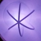
The bright spot at the center of the image jumped rapidly around within the grid. Although it is not clearly seen in the footage, there was an extension of that concentration that shot out to either the bottom or top chamber wall. This extension was clearly a jet of plasma and not similar to the damaging arcing experienced in Fusor 0.
The plasma was also still a pale purple-blue color, not the periwinkle that the camera captured. I am still in the process of fixing the white balance settings as I do not want to alter the images in post.
At this point, the camera stopped recording due to Sony’s limitations on recording time. I noticed this problem and re-activated the camera shortly after. Because I wanted to compare the images captured to a series of images available on fusor.net, I turned the ISO down to 400 to better match the camera settings used in the images.
Analysis:
The reason that I attempted to control current was to allow both numerical and visual comparison with a specific set of data on fusor.net. In that fusor.net example, at 100 microns and 5mA, the NST supplied 597V to the grid.³ In my run at 110 microns and 5mA, my NST supplied over 1600V to the grid.
The visual character of the plasma differs greatly from the fusor.net images as well.

I am not sure why the voltage was so high for Fusor 1.1, especially since both systems were powered with a rectified 12kV 30mA NST. Unfortunately, the fusor.net images do not contain data on the NST input voltage.
Interestingly, another plasma club aspiring fusioneer’s images seem closer to Fusor 1.1 than the bell jar system.
While his plasma visually looks closer to mine, the voltage and amperage are lower than both Fusor 1.1 and the bell jar demo. This is likely due in part to his usage of an x-ray transformer which his data less comparable, but is still interesting.
My current theory is that something about my system gives it significantly higher resistance compared to both the bell jar and other metal system. Ideally, there would be no resistance between the NST and ground other than the plasma within the chamber, so I will have to investigate further to determine the amount of resistance that actually exists.
Visually, an ISO of 400 made my plasma too dim and lowered the image’s dynamic range. There was a small “bugle jet” visible at 1600 volts during the test. I will increase my camera’s exposure for subsequent metering.
Viewport Residue:
After the test, I noticed a significant amount of deposition on the viewport that almost looked like shattered glass. I initially thought that this was the result of sputtering, but the most common description of sputtering that I have read is that of a gradual browning of the viewport⁵, not of large particles.

The residue on my viewport looks a lot more like bubbles of some liquid sprayed out onto the inside of the glass. I hope that this is condensation, but it is far more likely to be pump oil that was pulled out of the pump and into the chamber during the period between the pump deactivation and chamber venting. I was hoping to avoid this as cleaning the oil from the chamber will be very time consuming and likely necessary to reach 60 microns of vacuum again. To avoid this problem in the future, I will probably have to vent the chamber to atmosphere while the pump is still running.
Now that the Fusor 1.1 system is fully operable (assuming I sort out the vacuum oil issue), I plan to do many more tests controlling different variables relative to each other (otherwise known as: science). I just received the Precision D-25 pump that I ordered on eBay and am in the process of cleaning it and getting the necessary vacuum tubing and connectors to connect it to the chamber which will dramatically increase my vacuum capabilities.
At this point, I have a functional base system that I can build off incrementally to increase my capabilities even further all the way up to and far beyond simple fusion (I’m envisioning ion gun systems, metal activation, and more fun upgrades). More progress (and updates if I can find the time to write them) are hopefully soon to come!
Notes & Citations:
¹ https://fusor.net/board/viewtopic.php?t=13&f=7&sid=c03634687c8297889a4d61478c773b2d#p512
² Because the chamber is vented to atmosphere between tests to avoid pump oil backflow, it is likely that there will always be a glow cleaning phase of operation at the start of every test, but I hope that that phase gradually takes less time (especially after switching to the 1 CFM D-25).
³ https://fusor.net/board/viewtopic.php?f=24&t=2795
⁴ https://fusor.net/board/viewtopic.php?f=18&t=14138
⁵ https://www.fusor.net/board/viewtopic.php?f=24&t=14027, https://www.fusor.net/board/viewtopic.php?f=24&t=2916