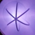
Last week, the rest of the fittings, adapters and other parts for Fusor 1 arrived! I put the chamber together last week, but due to a shipping mistake with Kurt J. Lesker (KJLC), did not receive a Conflat to KF adapter that I had ordered for another few days. Additionally, the leaded viewport that I ordered from them would not arrive until late December, so I cancelled that order and bought a non-leaded port on eBay. This might create some problems in the future, but I can add lead shielding if need be when I switch to the 30kV supply.
I decided to assemble and seal the chamber inside instead of in the workshop, because I wanted to avoid dust contaminating the inside of the chamber or interfering with the HV seals.
I went with Viton gaskets instead of copper ones because I knew that I will end up disassembling the chamber repeatedly in the near future as I iterate and improve the system and copper gaskets cannot be re-used more than 3 times.
One of the 6" to 2.75" CF flanges came preinstalled on the chamber and I was able to attach the other 6" to 2.75" CF flanges without much difficulty. If I get significant leakage, I will consider opening that connection and replacing the gasket, but if I do not encounter a problem I see no reason to worry about it.
The grid stalk is too short for my chamber so the grid does not sit in the middle of the chamber. I am a little worried that that will increase the chances of arcing to the chamber walls, but I do not think that the likelihood of this occurring outweighs the risk of elongating the stalk and permanently damaging the feed-through. In any case, I highly doubt that this arcing will occur at the (comparatively) low potential difference generated by the NST.
When I realized that the KJLC leaded viewport would take too long to arrive, I canceled the order and found a significantly cheaper unleaded viewport on eBay. Although this means that I will be dealing with a significantly worse attenuation constant¹ for x-rays exiting through the glass, I can simply angle the viewport (which will become a potentially deadly source of x-rays) away from myself and use extra lead shielding.
Is this a workable solution? Certainly.
Is this a good solution? No comment.
On Monday, the viewport arrived and I attached it to the chamber and tightened the bolts on all flanges. At this point, I believe that aside from the KF inlet for the thermocouple and the NPT insert for the vacuum line² the chamber is fully sealed.
I plan to do a pump-down test tonight to figure out how well the chamber is sealed. Although I know that there will be leaks between the chamber and pump (and inherent within the pump) that will likely prevent me from reaching below 1 torr, I think that the chamber itself will be relatively well sealed and that it will reach a lower vacuum than Fusor 0 as a result.
I am very excited to begin working on Fusor 1 in the coming days. As I’ve said before, the upgrade from my borosilicate tube Fusor 0 to the new Fusor 1 is monumental!
Notes & Citations:
¹ https://www.nist.gov/pml/x-ray-mass-attenuation-coefficients
² For more information as to why I am using this demonstrably leaky system, see my last post.
